How to Reduce Manufacturing Costs with Custom Aluminum Extrusions

Custom aluminum extrusions help you reduce manufacturing costs by improving material efficiency, simplifying designs, and streamlining production. You can consolidate multiple functions into a single part, optimize weight distribution, and enhance quality control. The table below shows how these benefits work in practice:

Benefit

Explanation

Consolidation of functions

Integrate several features into one profile, lowering assembly complexity and failure points.

Optimized weight distribution

Adjust thickness for performance, minimizing weight and energy use.

Improved quality control

Maintain consistent standards with dedicated partners.

Supply chain simplification

Reduce sourcing complexity and inventory management costs.


Key Takeaways

  • Custom aluminum extrusions improve material efficiency, reducing waste and lowering raw material costs.

  • Simplifying part designs cuts assembly time and labor costs, making production more efficient.

  • Multi-function profiles consolidate features, decreasing the number of components and minimizing secondary operations.

  • Adopting just-in-time manufacturing helps manage inventory costs and improves cash flow.

  • Choosing the right aluminum alloy enhances performance while keeping expenses low.


Key Factors That Influence Costs

When you plan a project with custom aluminum extrusions, you need to understand the main factors that shape your total manufacturing costs. Each factor can affect your budget and your ability to reduce manufacturing costs over time.


Die and Tooling Expenses

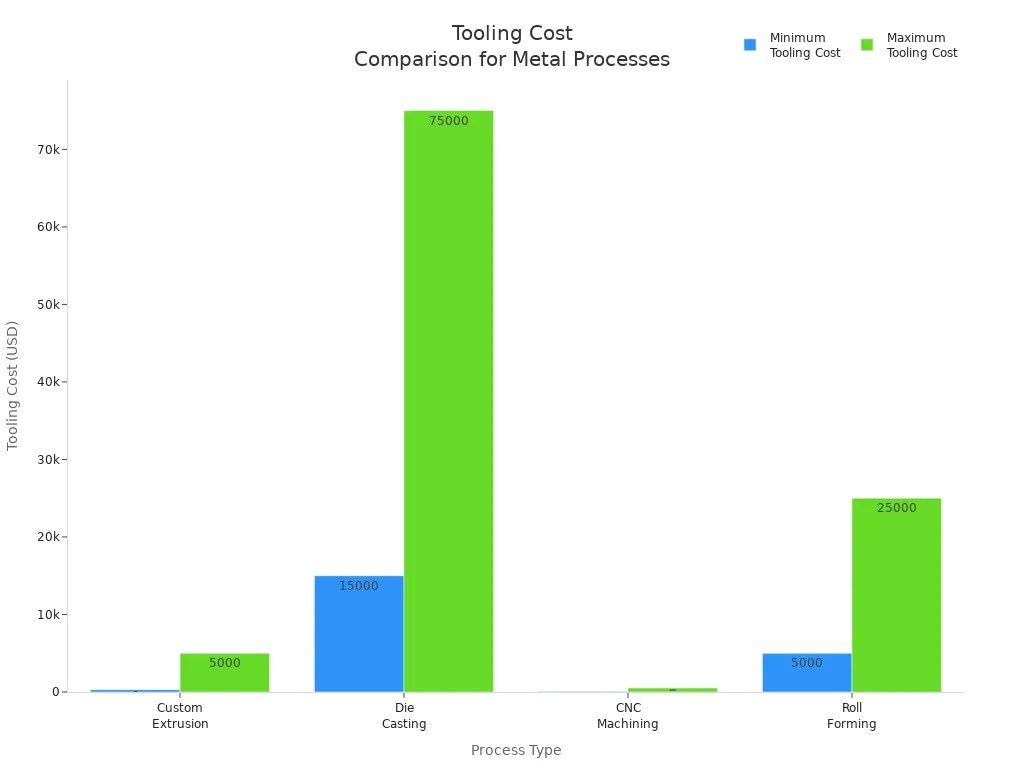
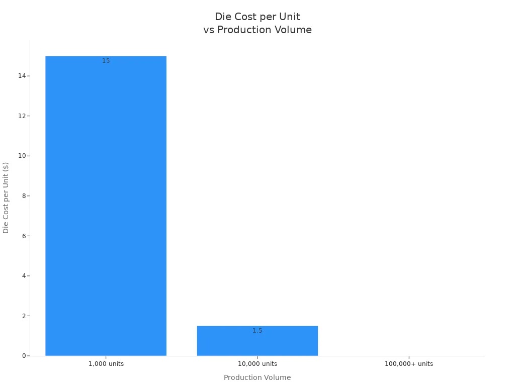
Custom dies and tooling are essential for creating unique aluminum profiles. The cost for a simple solid die usually ranges from $400 to $2,000, while complex hollow dies can reach $7,000 or more. Most projects fall between $1,250 and $1,950. These costs are much lower than those for casting or roll forming, which often exceed $15,000. For example, die casting tools can cost up to $75,000. As your production volume increases, the per-unit cost of the die drops, making custom extrusion a smart choice for medium to large runs.

Factor

Custom Extrusion

Die Casting

CNC Machining

Roll Forming

Tooling Cost

$300-$5,000

$15,000-$75,000+

$50-$500

$5,000-$25,000

Tip: Some suppliers may waive or refund die charges if you meet minimum order quantities.


Aluminum Material Prices

Aluminum prices play a major role in your project’s total cost. Material expenses can account for about 45% of your total sales revenue. Global demand, trade policies, and supply chain issues can cause prices to rise or fall quickly. For example, logistics disruptions and increased demand for sustainable materials have pushed prices higher in recent years. You should monitor market trends to make informed purchasing decisions and reduce manufacturing costs.


Labor and Production Costs

Labor and production costs for custom aluminum extrusions are usually stable and predictable. These costs depend on your region and the complexity of your profile. Direct labor for pressing or finishing can vary, and energy use often makes up about 25% of your total revenue. Producing a custom hollow profile by extrusion is much more affordable than machining the same part from solid billet. Operational efficiency and higher production volumes can help you control these costs and improve your bottom line.

  • Direct labor costs change with profile complexity.

  • Energy use scales with output.

  • Operational improvements can lead to significant savings.


How Custom Extrusions Reduce Manufacturing Costs
Material Efficiency

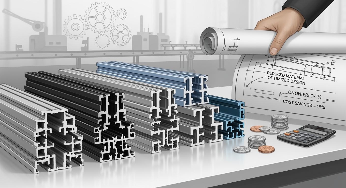
You can achieve significant material efficiency with custom aluminum extrusions. This process allows you to create profiles that match your exact requirements, which means you use only the material you need. By minimizing excess material, you lower raw material costs and generate less waste. This efficiency lets you reinvest savings into other parts of your business, boosting productivity and customer service. Streamlined production also reduces your reliance on outside vendors, which cuts transportation costs and overhead expenses. When you focus on material efficiency, you take a direct step to reduce manufacturing costs and improve your bottom line.

  • Custom extrusions allow complex shapes, which minimize the need for extra machining and tooling.

  • Using aluminum instead of stamped steel reduces weight, leading to lower shipping costs.

  • Less waste means fewer disposal fees and a smaller environmental footprint.


Simplified Part Design

Custom aluminum extrusions give you the flexibility to design parts that are easy to assemble and maintain. You can combine several features into one profile, which reduces the number of parts in your assembly. Fewer parts mean less time spent on assembly and fewer opportunities for errors. This approach helps you reduce manufacturing costs by cutting labor expenses and simplifying quality control.

"One of the best things you can do is to get your manufacturer involved early. Let the manufacturers who have been producing thousands of parts like yours look at your design and let them know how it’s going to be used, because they’re going to see something you don’t."

You can also save on tooling costs by simplifying your designs. For example, a complex hollow profile for a framing system might have a die cost of $2,800. By redesigning it into a four-slot hollow base with a snap-on rib cover, you could lower the tooling cost to $2,300. In another case, a complicated electronics enclosure became much more affordable when redesigned as a base channel and cover, cutting tooling investment by up to 50%.

  • Standardized extruded aluminum components make implementation easier.

  • Durable and modular aluminum framing reduces the need for frequent replacements.

  • Lighter parts lower shipping costs and improve safety during handling.


Multi-Function Profiles

You can design custom aluminum extrusions to perform multiple functions within a single profile. For example, you can include built-in hinges, screw bosses, or grooves. This integration reduces the number of separate components you need, which simplifies assembly and lowers production costs. When you combine several features into one part, you also reduce the need for secondary operations like welding or riveting.

  • Custom extrusions reduce assembly requirements by consolidating multiple components into a single profile.

  • The initial die investment becomes less significant as production volume increases, leading to greater cost efficiency.

  • High-volume production allows you to spread fixed costs over more units, which maximizes savings.

Production Volume

Die Cost per Unit

Cost Implication

1,000 units

$10-20

Higher per unit cost due to initial investment

10,000 units

$1-2

Significantly lower per unit cost as die cost is amortized

100,000+ units

Negligible

Minimal impact on overall cost, maximizing savings

When you use multi-function profiles, you not only reduce manufacturing costs but also streamline your entire production process. This strategy helps you stay competitive and responsive to changing market demands.


Process Efficiencies and Best Practices

Just-in-Time Manufacturing

You can improve your manufacturing efficiency by adopting just-in-time (JIT) practices. JIT means you produce and deliver parts only when you need them. This approach helps you avoid excess inventory and reduces storage costs. You also lower the risk of holding outdated or unused materials. When you use custom aluminum extrusions, you can plan production runs to match your demand. This flexibility lets you respond quickly to changes in your schedule or market needs. JIT also helps you keep your cash flow healthy because you do not tie up money in large inventories.


Minimizing Scrap and Waste

Reducing scrap and waste is a key way to reduce manufacturing costs. Custom aluminum extrusion processes use precise techniques to create parts that closely match your final dimensions. This accuracy means you throw away less material. You also save on energy because you do not need to reprocess as much waste. When you cut down on waste, you lower your disposal fees and free up valuable floor space for productive work. Less clutter in your production area helps prevent bottlenecks and keeps your workflow smooth.

  • Precise extrusion creates less scrap.

  • Lower waste means reduced tipping fees and waste management costs.

  • Effective segregation systems can cut disposal costs by up to 40% in the first year.

  • More space and less clutter improve productivity.


Fast Lead Times

Fast lead times give you a competitive edge. Custom aluminum extrusion orders usually have die build times of 3 to 5 weeks. You can expect sample extrusions about two weeks after the die is ready. This timeline is faster than many other manufacturing methods, such as injection molding. Quick turnaround means you start production sooner and reduce inventory holding costs. You also gain flexibility to respond to market changes. When you work with experienced manufacturers, you can often match the speed of stock orders, which helps you reduce manufacturing costs and improve operational flexibility.

Best Practice

Description

Use Extrusion Over CNC Machining

Extrusion is more cost-effective for uniform cross-section parts.

Leverage Experienced Machine Shops

Skilled shops ensure effective design and production.

Optimize Material Usage

Extrusion minimizes waste and saves money.

Streamline Manufacturing Steps

Fewer steps lower labor costs and reduce errors.

Tip: Plan your orders around typical lead times to avoid rush charges and keep your costs low.


Practical Tips for Cost Reduction

Alloy Selection

You can choose the right aluminum alloy to maximize performance and minimize expenses. Each alloy offers unique benefits for manufacturing applications. The table below shows the most cost-effective alloys for extrusion:

Alloy

Typical Applications

Min. Wall Thickness

Extrudability

Surface Finish Quality

6063-T6

Window frames, door systems, architectural trim

0.040" (1.0mm)

Excellent

Excellent—ideal for anodizing

6061-T6

Structural frames, aerospace fittings, automotive parts

0.050"-0.062" (1.3-1.6mm)

Good

Good—moderate anodizing quality

6005-T5

Rail car structures, truck frames

0.045"-0.055" (1.1-1.4mm)

Good

Good—suitable for industrial use

  • 6063 gives you better formability for complex shapes and superior surface quality at a lower cost.

  • 6061 provides higher strength and hardness, improved fatigue resistance, and versatility for demanding jobs.

  • 6005 balances strength and manufacturability, making it ideal for transportation.

Selecting the right alloy helps you reduce manufacturing costs by matching material properties to your project needs.


Advanced Design Tools

You can use advanced design tools and software to optimize your extrusion profiles. CAD systems and feature-based neural networks help you minimize errors and avoid costly rework. Virtual prototyping lets you test designs before production, saving time and money. Predictive analysis of material flow and thermal behavior identifies potential issues early. Streamlined design iterations lead to faster project completion and lower development costs.

  • Simulation software reduces the need for physical prototypes.

  • Early detection of design flaws prevents expensive mistakes.

  • Faster design cycles keep your project on schedule.


Secondary Operations

You can minimize or eliminate secondary operations by designing your extrusions effectively. The table below shows strategies that help you save money:

Strategy

Description

Avoid Undercuts

Features that require undercuts lead to costly secondary machining operations.

Limit Machined Details

Opt for post-extrusion finishes like anodizing or powder coating instead of milling complex patterns.

Specify Finishes Only When Needed

Use standard mill finishes for cost-effectiveness; reserve cosmetic finishes for essential aesthetic requirements.

Tip: Work with your extrusion partner to identify which features can be integrated into the profile and which finishes are truly necessary.

You can reduce manufacturing costs by limiting unnecessary machining and focusing on efficient finishing methods.


You can reduce manufacturing costs by focusing on smart design, efficient processes, and careful material selection. Review your current extrusion profiles and look for ways to combine features or minimize waste. Consult with extrusion experts to find new opportunities for savings.

Take action now to improve your production and stay competitive in the market.

  • Understand cost factors

  • Optimize your designs

  • Leverage process efficiencies


FAQ

What is the minimum order quantity for custom aluminum extrusions?

You can often start with as few as 500 to 1,000 pounds of material. Some suppliers offer lower minimums for prototypes or small runs. Always check with your extrusion partner for their specific requirements.

How do custom extrusions compare to standard profiles in cost?

Custom extrusions may have higher upfront die costs. You save money over time by reducing assembly steps, material waste, and secondary operations. For large production runs, custom profiles often cost less per unit than using multiple standard parts.

Can you recycle scrap from aluminum extrusion?

Yes, you can recycle almost all aluminum scrap from extrusion. Recycling aluminum saves energy and reduces raw material costs. Many manufacturers collect and reuse scrap directly in their production process.

What design features help reduce extrusion costs?

You can lower costs by:

  • Using uniform wall thickness

  • Avoiding deep channels or undercuts

  • Limiting sharp corners

Tip: Simple shapes extrude faster and require less finishing, which saves you money.
How to Tell if an Aluminum Profile Manufacturer Is Right for Your Project

You must choose the right aluminum profile manufacturer for your structural project. The global market will reach USD 126.67 Billion in 2025. Selecting an experienced aluminium profile supplier requires clear testing standards. You must evaluate technical match, production scale, and quality control. Your team should compare alloy choices like 6061 for strength against 6063 for smooth finishes. Custom tooling capacity ensures exact designs for custom aluminium extrusions and complex aluminium components. Partnering with Guang Ya aluminium provides strong supply chain reliability for your project. This framework covers structural feasibility, custom aluminum profiles, surface finishing options, total value, and high aluminium material purity from a top supplier.


Key Takeaways

  • Pick alloy 6061 for heavy strength or alloy 6063 for smooth metal surfaces.

  • Check plant equipment size to ensure workers can make your custom shape designs.

  • Demand clear factory testing reports to guarantee accurate parts and strong protective coatings.

  • Choose certified suppliers with large production lines to avoid long shipping delays.

  • Spread initial tool costs over large orders to save money on long projects.


Technical Capabilities of an Aluminum Profile Manufacturer

Evaluating Alloy Selection and Custom Aluminum Profiles

You must evaluate how an aluminum profile manufacturer selects structural alloys for your project applications. Selecting the correct alloy grade directly dictates structural safety, corrosion resistance, surface anodizing quality, and total component service life. Engineering teams usually choose between 6061 and 6063 grades under ANSI H35.1 temper standards and ASTM B221 specifications. Alloy 6061-T6 delivers high yield strength and ultimate tensile strength for heavy-duty frameworks. Alloy 6063-T6 provides a smoother exterior surface finish for architectural frame assemblies and window units. You can review key mechanical properties across standard tempers in the following reference table. This critical comparison helps engineers specify exact alloy temper requirements.

Property

Alloy 6061-T6

Alloy 6063-T6

Application Focus

Yield Strength

276 MPa

214 MPa

Load Capacity

Tensile Strength

310 MPa

241 MPa

Ultimate Resistance

Brinell Hardness

95

73

Surface Toughness

Shear Strength

207 MPa

152 MPa

Mechanical Stress

Alloy 6061 contains higher magnesium content than alloy 6063. This chemical composition yields high load-bearing capacity, but it increases die wear during extrusion. Conversely, alloy 6063 flows smoothly through complex multi-void dies. This material behavior allows rich customization for thin wall geometries and decorative finishes. When you collaborate with an experienced aluminium profile supplier, their engineering staff will analyze your design requirements. Valuable industry experience helps you select high durability profiles without paying extra for unneeded alloy strength. Selecting suitable raw material ensures your custom aluminium profiles deliver exceptional structural durability under demanding operational conditions.


Assessing Cross-Section Design and Tooling Capacity

Assessing cross-section feasibility requires evaluating press tonnage, wall thickness constraints, and profile circumscribing circle diameter limits. Leading extrusion plants like Guang Ya aluminium operate massive production facilities featuring 70 extrusion lines ranging from 600 to 5,500 tons. Their tooling catalog includes over 100,000 unique profile cross-sections for industrial aluminium projects. Higher extrusion press tonnage enables wider profile widths, larger circumscribing circle diameters, and thicker solid cross-sections. This equipment capacity allows manufacturers to execute complex aluminum shapes. However, sudden changes in wall thickness create uneven metal flow through the aluminium die. You should keep adjacent wall thickness variation within a 2:1 ratio to prevent surface tearing.

When evaluating supplier technical capabilities, you must assess several critical manufacturing standards:

  • Precision and repeatability: The facility must maintain tight dimensional tolerances matching standards like EN 755-9 or ASTM B221.

  • Tooling flexibility: The extrusion factory should switch complex multi-cavity dies efficiently to reduce project lead times.

  • Process control: Advanced heating controls preserve aluminium properties to maximize long-term component durability.

Your technical team must verify wall thickness feasibility before ordering custom production tooling. Standard industrial applications require minimum wall thicknesses between 1.2 mm and 1.6 mm to avoid warping thin aluminium sections. An expert aluminium profile supplier provides active design support during early engineering reviews. This collaborative guidance helps you optimize component customization while keeping tooling costs low. Partnering with a reliable aluminum profile manufacturer ensures your custom aluminum profiles satisfy all structural demands. Checking these engineering factors early prevents costly die redesigns during mass extrusion runs. Proper design review protects your project schedule and guarantees high quality manufacturing output.


Quality Assurance and Reliability Standards for Your Project


Inspecting Tolerances Surface Finishes and Testing Protocols

You must inspect surface finishes and dimensional tolerances to protect your structural project schedule. You should request detailed inspection logs from your extrusion partner before mass production. An experienced aluminium profile supplier conducts thorough surface quality audits before shipping. Advanced processing facilities verify surface treatments like anodizing, powder coating, and electrophoresis. These protective surface treatments prevent defects like dents or scratches on finished custom aluminium profiles. Non-destructive eddy-current gauges measure coating thickness according to ISO 7599 for anodized aluminium profile systems. Gloss meters check surface reflectance across every batch to ensure complete color uniformity. Electrophoretic coatings must maintain a precise thickness between 5 μm and 15 μm. Technicians perform cross-cut adhesion tests under ISO 2409 to confirm coating bond strength on powder coated profiles. Optional salt spray testing validates long-term corrosion resistance for over 1000 hours in harsh operational environments.

Quality Metric

Inspection Tool

Reference Standard

Coating Thickness

Eddy-current gauge

DIN 50981

Surface Roughness

Profilometer probe

EN 755-9

Adhesion Strength

Crosshatch tape test

ASTM D3359

Corrosion Defense

Salt spray chamber

ASTM B117

Rigorous physical testing guarantees structural durability under real working loads. An accredited national laboratory provides essential testing oversight for custom aluminium profiles. Advanced testing facilities analyze grain structure under microscope optics to prevent internal structural defects. A precision aluminium profile manufacturer like Guang Ya aluminium uses advanced testing instruments from Germany, the United States, and Taiwan. Their postdoctoral laboratory oversight confirms raw material purity and mechanical strength. Spectrometers analyze chemical compositions before casting to verify magnesium and silicon ratios. Technicians perform microhardness tests across cross-sections where hard anodizing must reach 300 HV minimum. Tensile testing machines pull profile samples to verify yield strength requirements. This scientific verification secures product quality before full manufacturing starts.


Verifying Industry Certifications and Mass Production Standards

You should verify factory certifications and compliance with recognized certifications to ensure long-term production consistency. Fundamental quality management for aluminium profile manufacturing relies on iso 9001 certification. Automotive supply chains require IATF 16949 standards for defect prevention. Environmental management systems follow international frameworks to reduce factory waste.

  • Mill Test Reports: Confirm alloy chemical composition and mechanical properties before extrusion begins.

  • Dimensional Reports: Verify wall thickness tolerances against european standards like EN 755-9.

  • Third-Party Audits: Independent inspection reports confirm product quality and structural durability.

Evaluating statistical process control methods shows how a supplier maintains product reliability for your primary aluminium extrusion project. Leading factories log every process parameter to track process capability indices. Production staff monitor billet heating temperature, extrusion speed, and cooling rates in real time. Automated alerting systems flag parameter deviations before non-conforming material reaches downstream processing. This active monitoring prevents defective profiles from entering final shipment. Batch lot control connects raw billet heating logs directly to final delivery documentation. You can request a First Article Inspection or Production Part Approval Process submission to verify dimensions against CAD models. A qualified supplier offers custom OEM aluminium extrusion and specialized aluminium extrusion solutions. These comprehensive factory controls follow global standards. These rigorous auditing steps ensure high quality for custom aluminum profiles and aluminum profiles for industrial applications.


Balancing Supply Chain Reliability with Project Costs


Analyzing Lead Times Post-Processing and Logistics

You must evaluate factory output scale to ensure supplier reliability for your industrial project. Large manufacturing facilities maintain continuous operations during volatile global market shifts. Guang Ya aluminium manages massive facilities yielding an annual output up to 700,000 tons. High volume production scale guarantees delivery reliability during sudden market demand spikes. Baseline lead times for custom aluminium profile orders typically range from 6 to 12 weeks. Tooling creation requires 2 to 4 weeks before extrusion begins.

Post-processing adds structural precision through custom fabrication and specialized surface finishing on raw aluminium billets. Integrated processing includes precision cutting, deburring, and CNC machining. Securing an experienced aluminium profile supplier reduces transit delays between independent sub-contractors. Complete full-service operations streamline ocean freight packaging. Steel bands optimize container space for bulk ocean delivery. Strategic shipping choices protect product durability during long ocean transit cycles. Proper logistics planning ensures direct delivery to your facility.


Evaluating Long-Term ROI and Supplier Engineering Support

Custom die investments require upfront capital during early product development for aluminium components. Solid dies cost between $1,000 and $2,000, while hollow dies range from $1,200 to $4,000. Spreading fixed tooling costs across high volume production runs lowers your per-unit expense. For example, a $1,500 die producing 100,000 feet of custom aluminium profile adds only $0.015 per foot. Amortizing initial tooling costs creates substantial long-term savings for your project. High volume primary aluminium extrusion yields significant operational reliability over time.

Strong supplier experience provides essential technical advantages throughout your project lifecycle. Partnering with a skilled aluminium profile supplier offers early design assistance, rapid prototyping, and detailed installation guidance. Early design review optimizes profile geometry to reduce scrap rates on structural aluminium sections. High manufacturing quality prevents costly production defects and unexpected operational downtime. Selecting a top aluminum profile manufacturer guarantees total value from concept to final delivery. Working with a dedicated aluminium profile supplier delivers superior service support for every custom aluminum profile.


Selecting the right aluminum profile manufacturer requires systematic project evaluation. You must review technical tooling, quality testing, and supply chain reliability. Effective project management requires conducting factory audits and requesting prototype samples before placing mass orders. This verification process secures fast delivery and excellent production service.

Partnering with an experienced aluminium profile supplier protects your structural needs. Guang Ya aluminium operates advanced facilities for custom aluminium extrusion profiles. Their team crafts high precision aluminium solutions. As a trusted anodized aluminium profiles manufacturer and powder coated aluminium profile supplier, Guang Ya aluminium delivers durable aluminium profiles for industrial applications. Choose Guang Ya aluminium today to receive reliable aluminum profiles for every custom aluminium application.


FAQ

How do you choose between 6061 and 6063 aluminium alloys?

You select 6061 aluminium for high load-bearing structural strength. You choose 6063 aluminium when your project requires smooth architectural surface finishes. Experienced engineering teams analyze your mechanical requirements to recommend the ideal custom aluminium profile alloy grade.


What tooling capacity indicates a reliable aluminium supplier?

You should choose an aluminium manufacturer with extensive die inventories. A major producer like Guang Ya aluminium operates 70 extrusion lines and holds over 100,000 cross-sections. This massive aluminium capacity guarantees flexible production schedules for every custom aluminium extrusion project.


How do surface finishes protect custom aluminium profiles?

Surface treatments like anodizing protect every aluminium frame from corrosion and environmental scratches. An accredited anodized aluminium profiles manufacturer verifies coating thickness with precision gauges. These high quality finishes maintain structural durability and long-term visual appearance across demanding outdoor job sites.


What quality testing guarantees precision aluminium extrusion performance?

You must request mill test reports and accredited laboratory verification. Advanced testing facilities evaluate chemical purity and tensile yield strength before mass manufacturing starts. These rigorous quality inspections ensure your industrial components satisfy global engineering standards and exact project specifications.


What Information Should You Provide When Requesting a Custom Aluminum Extrusion Quote?

You need to give all important information when you ask for a quote for a custom aluminum extrusion. This helps you get the right price and stops delays. The price of custom extrusions changes because of many things, like your full design and what you want. Important details are:

  • Correct drawings and the last version of your drawing

  • What alloy, temper, and surface finish you want

  • Important sizes and how exact they must be

  • How long each piece should be and how many you need

  • How the part should look

  • How you want it packed and how fast you need it

  • What file types you can send

If you leave out information, it can make your quote take longer or give you the wrong price. If you have questions about aluminum extrusion design or need help with a special aluminum part, Guang Ya Aluminium can look at your drawings and help you with the details.


Key Takeaways

  • Give clear and correct drawings to stop mistakes and help the factory know your design.

  • Say which alloy and temper you want, because these change how the part works and its price.

  • List all surface finishes you need and show which sides should look nice for the best look.

  • Clearly tell the cut lengths and how many you need so the supplier can plan making them and set the right price.

  • Use the right file types for your drawings so everyone can talk easily and get the right quote.


Drawings and Dimensions for Custom Aluminum Extrusions

When you ask for a quote, you need to give clear drawings. You also need to share exact details about your design. Good drawings help the factory know what you want. This stops mistakes from happening. Always send the newest version of your design. This helps you get the right price. It also makes sure your part will work.


Required Drawing Details

Your technical drawings should have some important things:

  • Show all main sizes and how close they must be.

  • List which aluminum extrusion alloys and finishes you want.

  • Add notes if you want to make building easier, like ways to use fewer steps.

  • Show the full size and shape of each part.

  • Pick the alloy and temper early in your plan.

These details help the factory check your needs. They also help them plan for good quality. If you need help, Guang Ya Aluminium can look at your drawings and give tips.


Specifying Dimensions and Tolerances

You must show all sizes and how close they must be on your drawings. This helps the factory keep good quality and find problems early. Careful checks at every step make sure your parts are good. They also make sure your parts work as you want. You should always use the rules that factories follow when you set how close sizes must be. Here are some common rules:

Standard

Description

ANSI H35.2

This is the main rule for sizes and how close they must be for aluminum mill products in the U.S. It gives exact sizes and limits.

ASTM B221

This rule is for aluminum and aluminum-alloy extruded products. It makes sure the material fits the size rules.

Aluminum Standards and Data (ASD)

This book puts size tables, alloy rules, and design tips in one place for engineers.

When you give all the details, you help the factory make your part in the best way. This saves time and money. If you have questions or need help with your RFQ, Guang Ya Aluminium can help you.


Alloy and Temper Selection

When you ask for a quote, you must pick the right alloy and temper. These choices change how your part works, how much it costs, and how easy it is to make. You should always tell the factory this in your rfq. This stops confusion and keeps things moving fast.


Choosing the Right Alloy

There are many alloys you can pick for custom aluminum extrusions. Each one has its own good points and best uses. Here is a table to help you see some popular choices:

Alloy

Tensile Strength

Strengths

Weaknesses

Applications

2024

455 – 483 MPa

Great strength, good formability

Poor corrosion resistance, poor weldability

Aircraft parts, gears, pistons

5052

193 – 290 MPa

Great formability, great corrosion resistance

Poor machinability

Marine equipment, appliances, tubes

6061

241 – 310 MPa

Great weldability, good machinability, good corrosion resistance

Average formability

Building products, automotive parts, furniture

You need to match the alloy to your project. For example, 6061 is strong and easy to weld. It works well for building and car parts. If you want better corrosion resistance, 5052 is a good pick.


Specifying Temper

Temper tells the factory how the alloy was treated. This gives the part special properties. Picking the right temper is just as important as picking the alloy. Some tempers, like T6, make the part strong. But T6 can crack if you bend it after extrusion. T5 is used for architectural parts. It gives a good balance of cost and strength.

Alloy/Temper

Yield Strength (psi)

Cost Implication

Complexity of Extrusion

6061-T6

35,000

Higher

Limited

6005-T5

37,700

Lower

More complex

When you send your rfq, always:

  • Say the alloy and temper you want.

  • Tell the product form, like tube or plate.

  • Give all sizes and tolerances.

  • List any standards or certificates you need.

Tip: Do not use hardness values instead of temper names. Always check that the alloy and temper you want exist.

Picking the right alloy and temper helps you get the best custom aluminum extrusion.


Surface Finish Requirements

When you ask for a quote, you must say what surface finish you want. The finish changes how your part looks. It also changes how long your part lasts. The finish can change the price too. Always tell the supplier which finish you want. Also say which surfaces will be seen.


Finish Options for Custom Aluminum Extrusions

There are many finish choices for custom aluminum extrusions. Each finish makes the part look different. Each finish gives a different level of protection. Some finishes are better for outside use. Others are good for inside parts. Here are some common finishes:

Finish Type

Visual Effect

Protection Level

Typical Application

Mill Finish

Dull, gray, tool marks

Low

Hidden parts, internal structures

Anodized

Matte, metallic sheen

Medium–High

Window frames, solar frames, facades

Powder Coat

Smooth, solid color

High

Railings, signs, building components

Brushed

Linear grain, matte

Medium

Trims, fixtures, display panels

Polished

Reflective, shiny

Low–Medium

Decorative or indoor visible parts

Painted

Glossy or custom tones

Medium

Custom branding or color themes

Think about where you will use your part. Outdoor parts need more protection. Anodizing or powder coating works best for these. If you want a certain color or shine, powder coating and painting are good choices. Some finishes, like PVDF liquid coating, cost more. These last longer in tough places.

Tip: Not every finish works with every alloy. Ask your supplier if you do not know which finish fits your alloy.


Cosmetic and Exposed Surfaces

You must show which surfaces need a cosmetic finish. Mark these spots on your drawings. If you want a special look, like a color or shine, write this in your request. For anodized parts, list the class and color. For powder-coated parts, give the color, shine, and any standards you need.

  • Move junction lines away from faces that must look perfect. This helps stop marks from showing.

  • Write down any special finish, like wood-look or brushed, so the supplier knows what you want.

  • Remember, finer finishes cost more and may take longer to make. For example, anodizing and powder coating can cost $1,200 to $1,400 per metric ton. Special finishes may cost even more.

Picking the right finish for your custom aluminum extrusion helps you get the look and performance you want. Giving clear details in your quote request saves time and stops mistakes.


Cut Lengths and Order Quantities

Specifying Cut Lengths

You must tell the supplier the exact cut length you want. This helps the factory pick the right tools and machines. Most people ask for pieces between 25 and 50 feet long. You can ask for shorter or longer pieces if needed. Always check your drawings to make sure the cut length is correct.

  • Write the cut length clearly on your drawing.

  • Tell the supplier if you need special length tolerances.

  • Ask about the best way to pack and ship your pieces.

If you use custom aluminum profiles for buildings or machines, you must give the right cut length. This helps the factory avoid mistakes and waste.


Indicating Quantities and Lead Times

You must tell the supplier how many pieces you need. The total number changes the price and how fast your order is made. Bigger orders help lower the cost for each meter. Suppliers can run machines better and get cheaper raw materials. You also save on shipping when you order more.

Factor

Impact of Order Quantity

Fixed Costs

Spread over more meters, so each meter costs less.

Production Efficiencies

Machines work better with big batches, so yield is higher.

Raw Material Procurement

Buying in bulk gets better prices from suppliers.

Shipping Costs

Full containers cost less per unit than small loads.

Supplier Negotiations

Big orders can mean discounts and better deals.

You should also tell the supplier when you need your order. Lead time depends on a few things:

Factor

Description

Tooling Status

If tooling already exists, lead time is much shorter.

Plant Workload

If the plant is busy, it may take longer to schedule your order.

Order Size

Bigger orders might take more time to finish and process.

Finish Requirements

Extra finishing steps can add more time to your order.

Material Availability

If raw materials are late, production can be delayed.

Customer-side Delays

If you change your design or approve late, lead time gets longer.

Tip: Give your delivery date when you ask for a quote. This helps the supplier plan and gives you a better timeline.

If you need extruded aluminum profiles for a big job, plan your order early. Clear details about cut lengths, quantities, and lead times help you get the best results.


Special Requirements for Custom Aluminum Extrusions

Packaging and Shipping Needs

You should tell the supplier how to pack and ship your custom aluminum extrusion. Clear instructions keep your parts safe while they travel. There are different ways to pack parts. Each way works best for certain needs. Here is a table with some common choices:

Packaging Style

Typical Use Case

Advantage

Strapped bundle

Long straight extrusions, large orders

Easy to handle, saves space

Cardboard wrap + guards

Small orders, high-finish or powder-coated

Surface protection

Wooden crate / pallet

Heavy, bulky, or mixed extrusion orders

Strong, stable for transit

Plastic sleeve or film

Corrosion-prone or long storage orders

Keeps out dust and moisture

You can ask for special packaging if your parts need extra care. For example, you might want cardboard wraps for shiny parts. Heavy custom aluminum profiles may need wooden crates. If you want samples or need artwork checked, tell the supplier. These requests can make your order take longer.

Special packaging and shipping requests can change your quote and how things are made. The table below shows how different things can affect lead time and planning:

Factor

Impact on Lead Time and Production

Clear Specifications

Helps avoid delays and ensures accurate quotes

Artwork Approval

Affects schedule due to checks needed before production

Packaging Samples

Adds extra lead time for confirmation

Complex Packaging Types

Require more planning and review time

Special Finishes

Increase planning time due to additional requirements

MOQ and Order Quantity

Affect material planning and production queue

Reorders

Can be faster if previous specifications are confirmed

Tip: Always give all packaging and shipping details when you ask for a quote. This helps the supplier plan and keeps your custom aluminum extrusions safe.


End Use and Application Details

You should tell the supplier how you will use your custom aluminum extrusion. This helps them know what you need and suggest the best choices. If you want extra work done on your parts, list these services:

  • Custom drilling

  • Punching

  • Countersinking

  • Cutting to length

  • Miter cutting

  • Bending or forming

Tell the supplier what your part will be used for. Here are some common uses for custom aluminum profiles:

  • Balustrades

  • Building and construction trim and framing pieces

  • Electrical components

  • Door and window frames

  • Furniture

  • Irrigation tubing

  • Marine applications

  • Piping

  • Railings

  • Recreation equipment

  • Sign frames

  • Storage tanks

  • Trailers

  • Truck frames

Adding services like anodizing, powder coating, assembly, or kitting can make your product better. These services make your custom aluminum extrusions stronger and easier to use. If you share how you will use your part, the supplier can give better advice and help you avoid mistakes.

Note: Special requests for packaging, shipping, or finishing can change your quote and how long your order takes. Clear communication helps you get the right custom aluminum extrusion for your project.


File Formats and Supporting Documents

When you ask for a quote, you must send your drawings in the right file type. This helps the supplier see your design without confusion. Using the correct file type makes it easier for engineers to check your project. It also helps them give you the right price.


Accepted Drawing File Types

Most aluminum extrusion suppliers use a few common file types. You should check with your supplier first, but these are the most popular:

  • .DXF

  • AutoCAD .DWG

  • Solid Works .STP

These file types let the factory look at your design closely. If you use another program, try to save your drawing as one of these types. Always send the newest version of your drawing so mistakes do not happen.

Tip: If you can, attach both a 3D model and a 2D drawing. This helps the supplier see your custom aluminum extrusions from every angle.


Additional Documentation

You should send more than just your drawing when you ask for a quote. Extra documents help the supplier understand what you need. This also makes the process faster. Here is a checklist to help you:

  1. Send your drawing or CAD file, like a STEP model and a PDF with sizes.

  2. Write down the alloy and temper you want.

  3. Tell your finish needs, like anodizing or powder coating.

  4. Show tolerances and mark important sizes.

  5. Say how many pieces you want or give different quantity choices.

  6. List any extra steps, like drilling or bending.

  7. Confirm how you want your parts packed.

  8. Write any inspection or certificate needs.

  9. Tell when you need your order and where it should go.

Complete documents help the supplier give you a quote faster and more correctly. When you send all the needed information, you avoid delays and mistakes. If you leave out details, the supplier may need to ask you more questions. This can make your project take longer.


Tips for a Complete Request for Quote

Submission Checklist

You can get a quote faster if you use a checklist. This makes sure you do not forget anything important. The table below shows what you need to include:

Checklist Item

Description

Dimensioned print

Add all important sizes and tolerances

Aluminum alloy & temper

Tell what material you want

Cut length(s)

Write the lengths you need for your parts

Cosmetically important surfaces

Point out surfaces that need to look good

Electronic file

Send files like igs, dxf, or dwg

Fabrication print

Add any details about how to make the part

Anodize/chem film/powder coat

Say if you need special surface treatments

Number of parts

Tell how many pieces you want

Packaging requirements

Write down any special packing needs

End use

Say what you will use the part for

Check off each item before you send your request. This helps the supplier know what you want for your custom aluminum extrusion and custom aluminum profiles. You will get answers faster and your quote will be more correct.


Common Mistakes to Avoid

People sometimes make mistakes when they ask for custom aluminum extrusion quotes. You can stop these problems by checking your papers and plans. Here are some mistakes people make:

  • If you leave out important sizes or tolerances, production can be late.

  • If you use unclear tolerance notes, there may be problems during checks.

  • If your profiles are too heavy, the cost goes up and they do not work as well.

  • If you do not think about die feasibility, your design may not be possible.

Tip: Look over your drawings and notes carefully. Make sure you know what extruded aluminum profiles can do and how they are made.

You can stop delays and extra costs by getting your papers ready and checking your plans. Talking clearly with the supplier helps you get the best results for your project.


You can get your custom aluminum extrusion quote faster if you give all the needed details. Use the checklist so you do not miss any steps, like drawings or surface finishing. When you talk clearly with the manufacturer, you get the results you want and do not have to redo your design. If you have questions, you can ask Guang Ya Aluminium for help. Giving all the right information helps you work well with your supplier and makes your project a success.

Required Information

Purpose

Drawings and CAD files

Accurate tooling and manufacturability

Alloy and finishing needs

Quality and compliance

Production volumes and timeline

Efficient planning and scheduling


FAQ

What information helps you get an accurate quote for custom aluminum profiles?

You should send clear drawings and exact sizes. Tell the supplier which alloy and temper you want. Say what surface finish you need. Write down the cut lengths and how many pieces you want. Also, tell them how you want your parts packed. This helps the supplier know your project and give the right price.

Can you request special finishes for extruded aluminum profiles?

Yes, you can ask for finishes like anodizing, powder coating, or painting. You should say what finish you want and the color. Tell which surfaces need to look good. This helps the supplier give you what you need.

Which file formats should you use for submitting drawings?

You should use .DXF, .DWG, or .STP files. These file types let the supplier check your drawings easily. Always send the newest version of your drawing.

How do order quantities affect your quote?

If you order more pieces, the price for each one is lower. Suppliers can plan better and buy materials in big amounts. You should tell the supplier how many pieces you need.

What if you need help with your design?

You can ask Guang Ya Aluminium for help. They look at your drawings and help you pick the best choices for your custom aluminum profiles.

Choosing the Right Machining Sequence to Reduce Distortion in Stainless Steel Components

Introduction

One of the most common challenges in precision stainless steel machining is controlling distortion throughout the manufacturing process. A component may leave the CNC machine with every dimension appearing to meet specification, only to deform slightly after unclamping, heat treatment, transportation, or final assembly. Even deviations of a few hundredths of a millimeter can affect sealing performance, assembly accuracy, or the overall reliability of industrial equipment.


While distortion is often associated with material quality or machining accuracy, one factor has an equally significant impact but is frequently overlooked—the machining sequence. The order in which machining operations are performed influences how internal stresses are released, how cutting forces are distributed, and how the workpiece responds throughout production.


For manufacturers producing stainless steel valve bodies, mounting plates, manifolds, brackets, structural components, or precision machine parts, selecting the proper machining sequence is one of the most effective ways to improve dimensional stability while reducing production costs.


Why Stainless Steel Is More Susceptible to Distortion

Compared with carbon steel or aluminum, stainless steel presents several characteristics that make deformation more difficult to control.


The material has relatively low thermal conductivity, causing heat generated during cutting to remain concentrated near the machining zone. As temperatures increase, localized thermal expansion may temporarily alter the shape of the workpiece.


Stainless steel also exhibits excellent toughness and work-hardening behavior. High cutting forces combined with repeated machining operations introduce additional stresses that may remain trapped within the component until material removal reaches a critical stage.


Large plates, welded structures, and thin-wall components are particularly vulnerable because internal residual stresses are often unevenly distributed throughout the material.


When machining operations remove material without a carefully planned sequence, these stresses may be released suddenly, causing bending, twisting, or dimensional movement.


Understanding Residual Stress

Every stainless steel component contains some degree of residual stress before machining begins.


Residual stress may originate from rolling, forging, welding, flame cutting, or previous manufacturing operations. Although invisible, these internal forces remain balanced while the material retains its original shape.


Machining gradually removes material that helps maintain this balance.


If one side of the workpiece is machined extensively while the opposite side remains untouched, stress distribution changes dramatically. Once the component is unclamped, the remaining stresses attempt to redistribute themselves, often resulting in distortion.


Understanding how residual stress behaves is therefore essential when planning machining operations.


Rather than removing material aggressively from one location, successful machining strategies aim to release stresses gradually and symmetrically.


Begin with Stable Datum Surfaces

A reliable machining sequence always starts by establishing stable datum references.


Before critical dimensions can be machined accurately, the workpiece must have consistent locating surfaces that remain unchanged throughout production.


Initial operations typically include rough face milling or reference surface preparation.


These datums provide accurate positioning for every subsequent machining process.


If datum surfaces are introduced too late or change between machining stages, positional errors accumulate and dimensional consistency becomes increasingly difficult to maintain.


Stable datums form the foundation of every precision machining sequence.


Rough Machining Before Precision Operations

One of the most important principles in distortion control is separating rough machining from finish machining.


Rough machining removes the majority of excess material while leaving a controlled machining allowance on all critical surfaces.


At this stage, higher material removal rates are acceptable because dimensional accuracy is not yet the primary objective.


Once rough machining is complete, the workpiece is allowed to stabilize. Depending on component size and application, manufacturers may perform stress-relief treatment or allow the part to rest naturally before continuing.


Only after the component has stabilized should precision machining begin.


This staged approach minimizes the likelihood that residual stress released during rough machining will affect finished dimensions.


Maintain Balanced Material Removal

Balanced machining is one of the most effective techniques for reducing distortion.


Instead of completely machining one side before moving to another, material should be removed as evenly as possible across the component.


For example, when machining a large stainless steel plate, alternating between opposite surfaces distributes cutting forces more uniformly.


Similarly, deep pockets should be machined progressively rather than removing the entire cavity in one operation.


This balanced approach minimizes uneven stress release while maintaining better dimensional stability.


Modern CAM software often assists engineers by optimizing machining paths that promote symmetrical material removal throughout production.


Delay Thin-Wall Machining Until the Final Stage

Thin-wall features present unique challenges because they possess relatively low rigidity.


If surrounding material is removed too early, thin sections become more susceptible to vibration and deformation during subsequent machining operations.


For this reason, experienced manufacturing engineers typically leave reinforcing material around delicate features until later stages of production.


The workpiece remains structurally stronger while major machining operations are completed.


Only after heavy cutting has finished are thin walls, narrow ribs, or lightweight structural features machined to their final dimensions.


This sequence greatly improves dimensional stability while reducing vibration during cutting.


Machine Critical Features Last

Critical functional features such as sealing surfaces, precision bores, locating holes, threaded interfaces, and bearing seats should generally be completed after the majority of heavy machining has been finished.


Early machining of these features increases the risk that later material removal will introduce slight dimensional changes.


Finishing these areas near the end of the machining sequence ensures they are produced after most internal stresses have already been released.


This approach improves dimensional consistency while reducing the need for secondary correction operations.


Consider the Relationship Between Machining and Fixturing

Machining sequence and fixture design must always work together.


Changing fixtures during production introduces opportunities for positioning variation and workpiece movement.


Whenever possible, multiple machining operations should be completed within a single setup.


Modern five-axis machining centers allow manufacturers to access several surfaces without repositioning the component.


Reducing setup frequency not only improves positional accuracy but also minimizes deformation associated with repeated clamping.


When fixture changes are unavoidable, engineering teams should carefully evaluate the sequence to ensure workpiece support remains adequate throughout every stage.


Practical Manufacturing Example

Shengtao Metal recently produced a series of stainless steel mounting bases for automated packaging equipment.


Each component required extensive pocket milling, multiple drilled holes, precision mounting surfaces, and several thin-wall structural sections.


Initial machining followed a conventional approach that completed one side before machining the opposite surface.


Although dimensional inspection during machining appeared acceptable, slight distortion became evident after unclamping.


Engineering analysis identified uneven stress release as the primary cause.


The machining sequence was redesigned.


Rough machining was distributed equally across both sides of the workpiece. Intermediate stabilization periods were introduced before finishing operations. Thin-wall features remained unmachined until the final stage, while precision mounting surfaces were completed only after all major material removal had been finished.


The revised process produced measurable improvements:

  • Dimensional stability improved by approximately 38%.
  • Flatness variation decreased significantly.
  • Assembly adjustments were reduced by over 20%.
  • Tool life improved because cutting loads became more consistent.
  • Overall production efficiency increased despite adding an intermediate stabilization stage.


The customer subsequently standardized this machining strategy for future production orders.


The Role of Digital Manufacturing

Modern digital manufacturing technologies are making machining sequence optimization increasingly sophisticated.


CAM simulation software allows engineers to evaluate cutting forces, material removal patterns, and machining order before production begins.


Virtual machining identifies areas where excessive stress release may occur, enabling process improvements without consuming raw material.


Machine monitoring systems also collect real-time production data that helps manufacturers continuously refine machining strategies across future production batches.


As digital manufacturing continues to advance, machining sequence optimization is becoming a data-driven engineering discipline rather than relying solely on operator experience.


Long-Term Benefits of Optimized Machining Sequences

Selecting the appropriate machining sequence generates benefits throughout the manufacturing process.


Manufacturers experience lower rejection rates, improved repeatability, reduced rework, and greater production efficiency.


Customers benefit from components with better dimensional consistency, easier assembly, improved sealing performance, and longer service life.


For OEM equipment manufacturers, stable machining processes contribute directly to product quality while reducing manufacturing costs over large production volumes.


Rather than viewing machining sequence as simply the order of operations, successful manufacturers increasingly recognize it as a strategic engineering tool for improving both quality and productivity.


Introduction

Distortion control remains one of the greatest challenges in precision stainless steel machining, but it is not determined solely by machine accuracy or material quality. The sequence in which machining operations are performed has a profound influence on how residual stresses are released and how the workpiece behaves throughout production.


By establishing stable datum references, separating rough and finish machining, balancing material removal, delaying thin-wall machining, protecting critical features until the final stage, and coordinating machining with fixture design, manufacturers can significantly improve dimensional stability while reducing production costs.


As industrial equipment continues to demand higher precision and greater reliability, optimizing machining sequences will remain an essential part of delivering high-quality stainless steel components that meet the increasingly demanding expectations of global OEM manufacturers.


Contact Shengtao Metal for Steel Product Solutions

If you are looking for reliable steel and metal product solutions, feel free to send us your inquiry.

Simply provide your specifications such as material grade, dimensions, quantity or application, and our team will respond quickly with professional support and a competitive quotation.

Email: stsalesman4@stmetal001.com

How Surface Flatness Influences the Performance of Precision Stainless Steel Assemblies

Introduction

When discussing precision machining, engineers often focus on dimensional tolerances, hole diameters, positional accuracy, or surface roughness. While these specifications are undoubtedly important, one critical characteristic is frequently underestimated during both design and manufacturing: surface flatness.


Flatness refers to how closely a machined surface conforms to a perfectly flat plane. Even when a component meets all dimensional requirements, excessive surface deviation can lead to sealing failures, assembly difficulties, uneven load distribution, vibration, and premature equipment wear.


For stainless steel assemblies used in industrial automation, fluid handling systems, processing equipment, robotics, and precision machinery, flatness is often just as important as dimensional accuracy. Components such as mounting plates, valve bases, machine frames, flange connections, and sealing surfaces rely on precise flatness to ensure reliable performance throughout their service life.


As industrial equipment continues to demand greater precision and higher operational reliability, controlling surface flatness has become an increasingly important part of modern CNC machining.


Understanding Surface Flatness

Surface flatness is one of the fundamental geometric characteristics defined by Geometric Dimensioning and Tolerancing (GD&T). Unlike thickness or length measurements, flatness evaluates the overall condition of an entire surface rather than individual dimensions.


A perfectly flat surface allows every point to lie within a specified tolerance zone without depending on any external reference.


For example, a stainless steel mounting plate may have a length tolerance of ±0.05 mm and still fail assembly if the surface bows upward by only 0.20 mm. Although the dimensions remain correct, the component will no longer provide uniform contact with mating parts.


This distinction makes flatness especially important for components that serve as assembly interfaces or sealing surfaces.


Why Flatness Is Critical in Industrial Equipment

Many industrial systems depend on large contact surfaces to transfer loads, maintain alignment, or create leak-free seals.


Consider a stainless steel flange installed within a high-pressure pipeline. If the flange surface is not sufficiently flat, the gasket experiences uneven compression during bolt tightening.


Some sections of the gasket may become over-compressed while others remain insufficiently loaded.


The result may include:

  • Fluid leakage
  • Reduced sealing life
  • Uneven bolt loading
  • Increased maintenance frequency


Similarly, robotic equipment relies on flat mounting plates to ensure accurate positioning.


Even a slight surface deviation can alter equipment alignment, reducing positioning accuracy and increasing calibration time during installation.


In automated manufacturing systems where repeatability is measured in microns, flatness directly influences machine performance.


Flatness and Structural Stability

Surface flatness also affects structural behavior after assembly.


When two components with imperfect surfaces are fastened together, tightening forces attempt to pull both parts into contact.


Instead of distributing loads evenly across the interface, contact occurs only at localized high points.


This uneven load distribution creates several problems:

  • Localized stress concentration
  • Bolt preload variation
  • Increased component deformation
  • Accelerated fatigue
  • Reduced structural rigidity


Over time, repeated loading cycles may loosen fasteners or create permanent deformation within the assembly.


Maintaining excellent flatness minimizes these risks while improving long-term mechanical stability.


Why Stainless Steel Presents Additional Challenges

Compared with carbon steel or aluminum, stainless steel introduces several machining characteristics that complicate flatness control.


The material generates relatively high cutting forces and retains heat near the cutting zone due to its low thermal conductivity.


Localized heat can produce temporary thermal expansion during machining.


If material removal is uneven, internal residual stresses may be released asymmetrically, causing the component to distort once clamping forces are removed.


Thin stainless steel plates are particularly susceptible to this phenomenon.


Even when machining operations appear successful during clamping, measurable deformation may occur after the workpiece is released from the fixture.


Large structural components present similar challenges because accumulated residual stress increases with component size.


The Relationship Between Material Removal and Flatness

Flatness begins with machining strategy.


Removing excessive material from one area before machining the opposite side often introduces stress imbalance.


Modern CNC machining therefore follows carefully planned material removal sequences.


Typical practice includes:

  • Rough machining
  • Stress stabilization
  • Semi-finishing
  • Final finishing


Material is removed gradually while maintaining balanced cutting forces across the workpiece.


Large components may even undergo intermediate stress-relief treatment before final machining to improve dimensional stability.


This approach significantly reduces the likelihood of distortion during finishing operations.


Fixture Design Plays a Key Role

Many flatness problems originate not from machining itself but from inadequate workholding.


If excessive clamping force is applied to a stainless steel plate, the component may deform elastically during machining.


While clamped, the surface appears perfectly flat.


However, after removing the component from the fixture, internal stresses are released and the plate returns toward its original shape.


The result is a finished part that no longer meets flatness requirements.


To prevent this, modern fixture systems distribute clamping pressure evenly across the workpiece.


Vacuum fixtures, modular support systems, hydraulic clamps, and customized soft jaws are commonly used to minimize deformation while maintaining sufficient rigidity during machining.


Proper fixture engineering allows components to retain their geometry after unclamping.


Cutting Parameters Influence Flatness

Machining parameters also contribute significantly to final surface condition.


Heavy cutting forces increase workpiece deflection and generate additional heat.


Selecting appropriate spindle speeds, feed rates, depth of cut, and cutting tools helps reduce thermal effects while maintaining machining stability.


Finishing passes are particularly important.


Rather than removing large amounts of material during the final operation, light finishing cuts minimize cutting forces and improve both flatness and surface quality.


Sharp cutting tools with proper geometry further reduce vibration and improve dimensional consistency.


Coolant management also plays a critical role by controlling cutting temperature throughout the machining process.


Inspection Methods for Surface Flatness

Because flatness directly affects product performance, manufacturers employ various inspection methods depending on component size and required accuracy.


Precision granite surface plates remain one of the most widely used reference standards for smaller components.


Dial indicators and electronic height gauges provide rapid flatness measurements during production.


For higher-precision applications, Coordinate Measuring Machines (CMMs) generate comprehensive three-dimensional surface data, allowing engineers to evaluate flatness across the entire workpiece.


Laser measurement systems are increasingly used for large structural components where contact measurement becomes less practical.


Inspection data collected during production also supports Statistical Process Control (SPC), enabling manufacturers to identify process trends before quality issues occur.


Practical Manufacturing Example

Shengtao Metal recently completed a machining project involving stainless steel mounting plates for automated inspection equipment used in a precision manufacturing facility.


Each plate supported multiple linear guide rails and high-resolution camera systems.


Although dimensional tolerances were relatively straightforward, the customer's primary concern involved maintaining exceptional surface flatness across the mounting interface.


Initial production trials revealed slight deformation after machining due to uneven stress release within the stainless steel plate.


To address this issue, engineers redesigned the machining process.


Material removal was balanced symmetrically across both sides of the plate, while fixture supports were redistributed to minimize localized deformation.


Finishing passes were performed using optimized cutting parameters with reduced material removal.


Every component subsequently underwent CMM verification before shipment.


Following implementation of the revised process:

  • Surface flatness improved by approximately 45%.
  • Assembly adjustments at the customer's facility were virtually eliminated.
  • Installation time decreased by nearly 20%.
  • Equipment alignment accuracy improved significantly.
  • Production consistency remained stable throughout batch manufacturing.


The customer later adopted the same machining strategy for several additional automation projects.


Long-Term Benefits of Flatness Control

Maintaining excellent flatness delivers benefits throughout the entire product lifecycle.


Manufacturers experience lower rejection rates, improved machining repeatability, and more stable production processes.


Equipment builders benefit from simplified assembly, better component interchangeability, and shorter installation times.


End users gain improved sealing performance, reduced vibration, enhanced structural rigidity, lower maintenance requirements, and longer equipment service life.


As manufacturing tolerances continue to tighten across industrial sectors, flatness is becoming a defining characteristic of high-quality precision components rather than simply another inspection requirement.


Introduction

Surface flatness is one of the most important geometric characteristics affecting the performance of precision stainless steel assemblies.


Although often overlooked in comparison with dimensional tolerances or surface finish, flatness directly influences sealing effectiveness, assembly accuracy, structural stability, equipment reliability, and long-term operational performance.


Achieving excellent flatness requires careful coordination of material selection, machining strategy, fixture design, cutting parameters, and inspection methodology. Every stage of the manufacturing process contributes to the final result.


For manufacturers producing precision stainless steel components, investing in advanced flatness control is not only a quality improvement strategy but also a practical way to reduce production costs, improve customer satisfaction, and support increasingly demanding industrial applications.


Contact Shengtao Metal for Steel Product Solutions

If you are looking for reliable steel and metal product solutions, feel free to send us your inquiry.

Simply provide your specifications such as material grade, dimensions, quantity or application, and our team will respond quickly with professional support and a competitive quotation.

Email: stsalesman4@stmetal001.com

How to Specify Seamless Steel Pipe for High-Pressure Industrial Systems

Introduction

In industrial infrastructure, the integrity of a high-pressure system depends on its piping components. Specifying seamless steel pipe for high-pressure systems is a challenge for procurement officers and engineers. Seamless pipes are preferred because they lack the longitudinal weld seam found in welded pipes, a potential weakness under stress. Specifying the right pipe requires understanding manufacturing processes, standards, and environmental conditions.


The Importance of Seamless Manufacturing in High-Pressure Applications

Seamless steel pipe is made by heating a solid steel billet and piercing it with a mandrel to create a hollow shell. This shell is then rolled to the desired diameter and wall thickness. This provides a uniform grain structure throughout the pipe wall, essential for maintaining integrity under high internal pressures. Unlike welded pipes, where the heat-affected zone can have different properties, seamless pipes offer predictable performance. The absence of a weld seam eliminates the risk of preferential corrosion at the joint, which is a common failure mode in aggressive industrial environments. Furthermore, the hot-rolling process used in seamless manufacturing refines the steel's grain structure, enhancing its toughness and resistance to sudden pressure surges or thermal shocks.


For industrial buyers, understanding this is the first step. High-pressure systems in oil, gas, and power generation require a reliability that only seamless pipes provide. When a system operates at high PSI, small imperfections can lead to failure. Therefore, specifications must require a seamless product manufactured to international standards. The manufacturing process also allows for a wider range of wall thicknesses compared to welded pipes, providing engineers with more flexibility in their design calculations. This is particularly important for deep-sea oil extraction or high-pressure chemical reactors where standard schedules may not be sufficient.


Decoding ASTM and API Standards for Seamless Pipe

Selecting the right industry standard is critical. ASTM and API provide the framework for these specifications. For high-pressure industrial applications, ASTM A106 and ASTM A53 are the primary standards, while API 5L is the benchmark for pipelines. These standards define not only the chemical and mechanical properties but also the required testing and inspection protocols. Understanding the nuances between these standards can prevent costly over-specification or dangerous under-specification.


ASTM A106 Grade B is the most common specification for high-temperature seamless carbon steel pipe. It is used in power plants and boilers where pipe faces high pressure and heat. Grade B has higher strength than Grade A, making it suitable for rigorous use. When specifying A106, ensure you request "seamless" specifically, as A53 can be either. A106 pipes are specifically killed steels, meaning they are fully deoxidized during the melting process, which results in a more uniform and stable microstructure suitable for high-temperature welding and forming operations.


API 5L covers seamless and welded line pipe for petroleum and gas industries. It includes grades like X42 and X52, indicating yield strength. For high-pressure transmission, specifying high-grade API 5L seamless pipe allows for thinner walls while maintaining safety margins, reducing material weight and cost. API 5L also includes more stringent requirements for toughness testing and dimensional tolerances, making it the preferred choice for cross-country pipelines where the pipe must withstand environmental stresses and potential ground movement.


Determining Pipe Dimensions: OD, Schedule, and Wall Thickness

Specifying pipe dimensions is where errors occur. Pipe sizes are referred to by Nominal Pipe Size (NPS) and Schedule (SCH). NPS relates to the approximate internal diameter for small sizes and actual outside diameter (OD) for larger ones.


The "Schedule" defines wall thickness. Common schedules include SCH 40, SCH 80, and SCH 160. For high-pressure systems, SCH 80 and above are frequently required. Designers must calculate the minimum wall thickness based on pressure, material stress, and mill tolerance (typically +/- 12.5% for seamless).


Always provide the NPS, Schedule, and decimal wall thickness. This ensures the supplier provides a product meeting safety calculations. For example, a 6-inch NPS pipe in SCH 80 has a different rating than in SCH 160. Misunderstanding these designations can lead to under-specifying or over-specifying.


Material Chemistry and Mechanical Properties

A seamless pipe's performance results from its chemistry and mechanical properties. Carbon steel is the standard for high-pressure use due to its cost-effectiveness and strength. Adding manganese or silicon can enhance toughness and weldability.


In specification documents, reference required chemical limits and test results. ASTM A106 Grade B specifies limits for carbon, manganese, and other elements. These must be balanced to ensure the pipe can be welded while maintaining strength.


Mechanical properties like tensile strength and yield strength are important. Tensile strength is the maximum stress the material can withstand, while yield strength is where it begins to deform. For high-pressure systems, a high yield-to-tensile ratio is desirable, accompanied by sufficient ductility to prevent brittle failure under pressure surges.


Environmental Considerations and Corrosion Allowances

High-pressure systems are often in corrosive environments like offshore platforms. Carbon steel is susceptible to oxidation and pitting. Engineers often include a "corrosion allowance"—additional thickness added to the calculated minimum wall thickness to account for expected metal loss. For example, if a system is expected to lose 0.1mm per year over 20 years, specify an additional 2mm of wall thickness.


In extreme environments, carbon steel may be replaced with stainless steel. Grades like 304L or 316L offer resistance but are more expensive. For high-pressure hydrogen service, specialized seamless pipes with controlled hardness are required to prevent cracking.


Testing and Quality Assurance Requirements

Specifications must include testing and quality assurance. Every length of seamless pipe should undergo a hydrostatic test, where it is pressurized to a level higher than its rating to verify integrity.


Non-destructive examination (NDE) methods are also specified. Ultrasonic testing (UT) can detect internal flaws and verify thickness consistency. For critical systems, 100% UT may be required to ensure no laminations exist.


Buyers should require Mill Test Reports (MTRs) for every batch. An MTR provides the actual chemical and mechanical results for the specific heat of steel used. This provides traceability and serves as proof of compliance with standards. Without an MTR, a pipe is an unknown quantity.


Logistics, Handling, and Storage Specifications

Logistics involve the handling and delivery of the product. High-pressure pipes are heavy and can be damaged if not secured. Specifications should include requirements for end protection, like plastic caps, to prevent damage to beveled ends used for welding.


Storage is also important. Carbon steel pipes are usually coated with a temporary rust preventative. If stored outdoors, the specification might require a more robust coating or specific stacking to prevent water pooling. Clear marking is also required; each pipe should be stenciled with the manufacturer, specification, size, and heat number for traceability.


Conclusion: A Holistic Approach to Piping Specification

Specifying seamless steel pipe is a technical process requiring a holistic view of design, material, and regulation. By focusing on manufacturing, adhering to standards, and insisting on testing, buyers can ensure the safety and longevity of their infrastructure.


The collaboration between engineers and procurement is key. While the engineer defines technical requirements, procurement ensures suppliers meet them and provide documentation. A well-specified seamless pipe is the foundation of a safe industrial operation. It is the invisible backbone of our modern world, quietly supporting the critical processes that power our homes, fuel our transport, and maintain our global industrial strength. By treating the specification process with the technical respect it deserves, professionals can build systems that are not only high-performing but also fundamentally safe for the people who operate them every day.


Contact Shengtao Metal for Steel Product Solutions

If you are looking for reliable steel and metal product solutions, feel free to send us your inquiry.

Simply provide your specifications such as material grade, dimensions, quantity or application, and our team will respond quickly with professional support and a competitive quotation.

Email: stsalesman4@stmetal001.com

Stainless Steel Pipe Grades Explained 304, 316, 321, and Duplex for Industrial Buyers

Introduction

In the diverse landscape of industrial materials, stainless steel stands out for its exceptional durability and resistance to corrosion. However, "stainless steel" is not a single material but a broad category encompassing numerous alloys, each tailored for specific performance characteristics. For industrial buyers, Stainless Steel Pipe Grades Explained: 304, 316, 321, and Duplex for Industrial Buyers is a vital guide to navigating these options. Choosing the wrong grade can lead to premature failure, increased maintenance costs, or unnecessary expenditure on over-engineered materials. Understanding the chemistry and application of each grade is the key to successful piping procurement.


Grade 304: The Versatile Standard

Grade 304 stainless steel, often referred to as "18/8" due to its 18% chromium and 8% nickel content, is the most common grade used in piping systems worldwide. Its popularity stems from its excellent balance of corrosion resistance, formability, and cost-effectiveness. In many general industrial applications where the environment is not excessively corrosive, 304 stainless steel pipe provides a reliable and long-lasting solution.


For buyers, 304 is the "go-to" grade for food and beverage processing, dairy equipment, and pharmaceutical piping. Its smooth surface finish is easy to clean and sanitize, preventing bacterial growth. Additionally, it has good cryogenic properties, making it suitable for low-temperature applications. However, it is important to note that 304 is susceptible to pitting and crevice corrosion in chloride-rich environments, such as coastal areas or systems involving high concentrations of salt. When a project involves such conditions, moving to a higher grade is necessary.


Grade 316: Enhanced Corrosion Resistance

When 304 stainless steel reaches its limits, Grade 316 is typically the next choice. The primary difference between the two is the addition of 2% to 3% molybdenum in Grade 316. This small change in chemistry significantly enhances the material's resistance to chloride-induced corrosion and pitting. This makes 316 stainless steel pipe the standard for marine applications, chemical processing plants, and environments where the piping is exposed to de-icing salts or harsh industrial chemicals.


Industrial buyers often specify 316L (the "L" standing for Low Carbon) for piping that requires extensive welding. Standard 316 can experience "sensitization" during welding, where chromium carbides form at the grain boundaries, reducing corrosion resistance. The low carbon content of 316L minimizes this risk, ensuring the welded joints remain as corrosion-resistant as the base metal. While 316 is more expensive than 304, the investment is often justified by the reduced risk of leaks and the extended service life in aggressive environments.


Grade 321: High-Temperature Stability

For applications involving high temperatures, neither 304 nor 316 may be sufficient. Grade 321 stainless steel is an austenitic grade that is stabilized by the addition of titanium. This stabilization prevents the formation of chromium carbides during exposure to temperatures in the "sensitization range" of 800°F to 1500°F (427°C to 816°C). Consequently, 321 stainless steel pipe is primarily used in high-temperature environments such as aircraft exhaust manifolds, heat exchangers, and boiler tubes.


The advantage for industrial buyers is that 321 maintains its mechanical properties and corrosion resistance even after prolonged exposure to heat. While it shares many characteristics with 304, the titanium content makes it far superior for systems that undergo thermal cycling or operate continuously at elevated temperatures. When specifying 321, buyers should be aware that it is less common than 304 or 316, and lead times might be longer. However, for high-heat industrial processes, it is a critical specification for safety and reliability.


Duplex Stainless Steel: Strength and Resilience

Duplex stainless steel is a unique class of alloys that combines the best features of both austenitic (like 304/316) and ferritic stainless steels. Its microstructure consists of approximately equal parts of austenite and ferrite. This "dual-phase" structure gives Duplex pipes significantly higher strength—often double that of standard austenitic grades—and exceptional resistance to stress corrosion cracking (SCC).


For industrial buyers in the oil and gas, desalination, and petrochemical industries, Duplex grades like S31803 or S32205 are highly valued. They are particularly effective in handling high-pressure fluids containing chlorides and hydrogen sulfide. Because of its high strength, designers can often specify thinner-walled Duplex pipe compared to 316, which can lead to weight savings and potentially lower overall material costs despite the higher price per pound. Duplex stainless steel is the preferred choice for demanding structural and piping applications where both corrosion resistance and high mechanical strength are required.


Chemical Composition and Its Impact on Performance

The performance of these stainless steel grades is governed by their precise chemical composition. Chromium is the essential element that creates the "passive layer" of chromium oxide on the surface, which prevents rust. Nickel adds ductility and improves corrosion resistance in reducing environments. Molybdenum, as mentioned, is the key to chloride resistance.


Industrial buyers must be diligent in reviewing Mill Test Reports (MTRs) to ensure the material meets the specified limits for these elements. For instance, a "316" pipe with molybdenum at the very bottom of the allowed range may not perform as well in a harsh chemical environment as one at the top of the range. Understanding these nuances allows buyers to have more technical conversations with suppliers and ensure the product delivered is fit for the intended purpose.


Mechanical Properties: Beyond Corrosion Resistance

While corrosion resistance is often the primary reason for choosing stainless steel, mechanical properties cannot be ignored. Tensile strength, yield strength, and elongation define how the pipe will behave under physical stress. Austenitic grades like 304 and 316 are known for their excellent toughness and ductility, even at very low temperatures. They do not become brittle, which is a major advantage for safety.


In contrast, Duplex grades offer much higher yield strengths, making them suitable for high-pressure systems where reducing wall thickness is a priority. However, Duplex steels have a more limited temperature range than austenitic grades, typically becoming brittle if used above 600°F (315°C) for extended periods. Buyers must match the mechanical profile of the grade to the operational pressures and temperatures of their specific piping system to avoid mechanical failure.


Fabrication and Welding Considerations

The choice of stainless steel grade also impacts how the pipe can be fabricated and installed. Austenitic grades (304, 316, 321) are generally easy to weld using standard techniques, although 321 requires specific filler metals to maintain its stabilized properties. The "L" grades (304L, 316L) are preferred for welding to prevent intergranular corrosion in the heat-affected zone.


Duplex stainless steel is more challenging to weld. It requires careful control of the heat input and cooling rates to maintain the correct balance of austenite and ferrite in the weld metal. If the balance is lost, the corrosion resistance and toughness of the joint can be compromised. When procurement teams specify Duplex pipe, they must also ensure that the installation contractors have the necessary expertise and procedures to handle this specialized material.


Cost vs. Value in Grade Selection

Cost is always a factor in industrial procurement, but with stainless steel, the cheapest option is rarely the best value. 304 is the most affordable, but using it in a chloride environment will lead to leaks and expensive downtime. 316 is a moderate step up in price but offers significant protection in most industrial settings. 321 and Duplex are specialized materials with higher price tags, but they are indispensable for high-temperature or high-stress applications.


Buyers should perform a Life Cycle Cost (LCC) analysis. This involves considering not just the initial purchase price, but also the expected lifespan, maintenance costs, and the cost of potential system failures. Often, spending 20% more on a higher grade of stainless steel pipe can save thousands of dollars in repair costs and lost production over the life of the facility.


Conclusion: Making the Right Choice

Understanding the nuances of stainless steel pipe grades is a fundamental skill for anyone involved in industrial piping procurement. From the versatile 304 to the specialized Duplex alloys, each grade has a specific role to play in modern infrastructure. By considering the environmental conditions, operational temperatures, and mechanical requirements of the project, buyers can select the grade that offers the best performance and value.


The key to success lies in detailed specifications and working with reputable suppliers who can provide full material traceability. Whether it is the high-temperature stability of 321 or the marine-grade resilience of 316, the right stainless steel pipe grade is the bedrock of a safe and efficient industrial system. Informed decision-making today prevents the costly failures of tomorrow, ensuring that industrial operations can continue to run smoothly in even the most challenging environments.


Contact Shengtao Metal for Steel Product Solutions

If you are looking for reliable steel and metal product solutions, feel free to send us your inquiry.

Simply provide your specifications such as material grade, dimensions, quantity or application, and our team will respond quickly with professional support and a competitive quotation.

Email: stsalesman4@stmetal001.com

Understanding Steel Pipe OD, Wall Thickness, Schedule, and Weight Calculations

Introduction

For anyone involved in the engineering, procurement, or installation of industrial piping systems, a precise understanding of dimensions is non-negotiable. Understanding Steel Pipe OD, Wall Thickness, Schedule, and Weight Calculations is a fundamental skill set that ensures the safety, efficiency, and cost-effectiveness of any project. While the terms may seem straightforward, the interrelationship between Nominal Pipe Size (NPS), Outside Diameter (OD), and the various "Schedules" can be confusing for those new to the industry. This guide provides a comprehensive breakdown of these critical measurements and the mathematics used to determine a pipe’s physical properties.


The Foundation: Nominal Pipe Size (NPS) vs. Outside Diameter (OD)

The first step in understanding pipe dimensions is the distinction between Nominal Pipe Size (NPS) and the actual Outside Diameter (OD). NPS is a North American set of standard sizes for pipes used for high or low pressures and temperatures. The "nominal" part means that the size is a name rather than an exact measurement for smaller pipes. For pipes with an NPS of 1/8 to 12 inches, the NPS value is not equal to the actual OD. For example, a pipe with an NPS of 2 inches actually has an outside diameter of 2.375 inches.


However, for pipes with an NPS of 14 inches and larger, the NPS is exactly equal to the OD. A 14-inch NPS pipe has an OD of precisely 14 inches. In the international community, the metric equivalent is known as Diameter Nominal (DN), which uses millimeters (e.g., DN 50 is the equivalent of NPS 2). For industrial buyers, always verifying the actual OD in decimals or millimeters is critical, especially when coordinating with valves, fittings, or structural supports.


Defining Wall Thickness and the Schedule (SCH) System

Once the OD is established, the next critical dimension is the wall thickness. In the piping industry, wall thickness is typically defined by a "Schedule" number, such as SCH 40, SCH 80, or SCH 160. The Schedule system is a dimensionless number that relates to the wall thickness of the pipe. It was developed to provide a standardized way to specify pipe strength without needing to list every possible decimal thickness.


As the Schedule number increases, the wall thickness of the pipe increases while the outside diameter remains constant. This means that as you move from SCH 40 to SCH 80, the pipe gets thicker, but the internal diameter (ID) gets smaller. It is a common misconception that the wall thickness for a specific Schedule is the same across all pipe sizes. In reality, the actual decimal thickness for "SCH 40" changes depending on the NPS. For instance, the wall thickness of an NPS 2 SCH 40 pipe is 0.154 inches, while for an NPS 6 SCH 40 pipe, it is 0.280 inches. Understanding this variation is vital for accurate pressure rating calculations.


Calculating Internal Diameter (ID)

While OD and Wall Thickness are the primary specified dimensions, the Internal Diameter (ID) is what determines the flow capacity of the pipe. The ID is not typically specified directly but is calculated from the OD and the wall thickness. The formula is simple: Internal Diameter = Outside Diameter - (2 x Wall Thickness).


For engineers, calculating the ID is the first step in determining the flow velocity and pressure drop within a system. In high-pressure applications where a thicker wall (like SCH 160 or XXS) is required for strength, the ID can be significantly smaller than the nominal size would suggest. This can impact the overall efficiency of the system and may require the designer to move to a larger NPS to achieve the desired flow rate. Always perform this calculation to ensure the chosen pipe meets the hydraulic requirements of the project.


Theoretical Weight Calculation Formulas

The weight of a steel pipe is a critical factor for logistics, structural support design, and cost estimation. Steel pipe is generally sold by weight, so being able to calculate the theoretical weight is an essential skill for procurement professionals. The weight of a pipe is determined by the volume of steel in the pipe wall and the density of steel.


For carbon steel pipes, the standard formula used in the industry (expressed in pounds per foot) is: Weight (lb/ft) = 10.69 x (OD - t) x t, where "OD" is the outside diameter in inches and "t" is the wall thickness in inches. In the metric system, the formula (expressed in kilograms per meter) is: Weight (kg/m) = (OD - t) x t x 0.02466, where "OD" and "t" are in millimeters. This constant (0.02466) is derived from the density of steel, which is approximately 7,850 kg/m³.


The Importance of Mill Tolerance in Calculations

When performing these calculations, it is important to remember that they are "theoretical." In reality, no pipe is manufactured to perfectly exact dimensions. Industry standards like ASTM A106 or API 5L allow for a "mill tolerance," which is the permissible deviation from the specified wall thickness. For most seamless steel pipes, the mill tolerance is +/- 12.5%.


This means that a pipe specified with a 10mm wall could actually have a wall thickness anywhere from 8.75mm to 11.25mm. When calculating weight for shipping or structural loads, it is best practice to account for this tolerance. For pressure containment calculations, engineers always use the "minimum wall thickness" (nominal minus the 12.5% tolerance) to ensure a sufficient safety margin. Overlooking mill tolerance can lead to under-designed systems or unexpected weight issues during transport.


Comparing Standard Weight (STD), Extra Strong (XS), and Double Extra Strong (XXS)

In addition to the Schedule numbers, you will often encounter terms like STD (Standard), XS (Extra Strong), and XXS (Double Extra Strong). These were the original designations for wall thickness before the Schedule system was fully adopted. For many pipe sizes, these terms correlate directly with specific Schedule numbers.


For example, for NPS sizes up to 10 inches, STD is the same as SCH 40. For NPS sizes up to 8 inches, XS is the same as SCH 80. However, as the NPS increases, these correlations change. XXS is always a very heavy wall thickness, often thicker than SCH 160. While the Schedule system is more common in modern specifications, many legacy projects and specific industries still use STD, XS, and XXS. Understanding how these terms map to decimal thicknesses is essential for anyone working with a variety of piping standards.


Using Pipe Weight Tables and Charts

While manual calculations are important for understanding the principles, most professionals use pipe weight tables or charts for day-to-day work. These tables list the OD, Wall Thickness, ID, and Weight per foot/meter for every NPS and Schedule combination. They are an invaluable resource for quick reference and for verifying supplier quotes.


However, when using these charts, always double-check the material density used for the weight calculation. Most standard charts are based on carbon steel. If you are working with stainless steel or specialized alloy pipes, the weight will be slightly different because the density of the material varies. For example, the density of 304 stainless steel is approximately 7,930 kg/m³, which is slightly higher than carbon steel. Always adjust your calculations if you are working with non-carbon steel materials.


Practical Application in Procurement and Logistics

For a procurement officer, understanding these calculations is vital for verifying that the material received matches the order. When a shipment of pipe arrives, one of the first quality checks is to measure the OD and wall thickness at several points and then weigh a sample length. If the weight is significantly lower than the theoretical calculation (even accounting for mill tolerance), it may indicate that the wall thickness is below the required specification.


From a logistics perspective, knowing the total weight of a pipe order is essential for planning transport. It determines how many trucks are needed, what type of crane is required for unloading, and how the pipe should be stacked in the warehouse. Accurate weight calculations prevent costly delays and safety hazards during the handling of large-scale piping orders.


Conclusion: Precision Leads to Project Success

In the industrial piping world, precision is the foundation of safety and reliability. By mastering the concepts of OD, wall thickness, schedules, and weight calculations, professionals can ensure that their piping systems are engineered to the highest standards. Whether you are calculating the flow capacity of a distribution line or the shipping weight of a transcontinental pipeline, these fundamental measurements are the tools of the trade.


Understanding the nuances of nominal sizes, the variations in schedule thicknesses, and the impact of mill tolerances allows for more informed decision-making and better communication between engineers, suppliers, and contractors. In the end, a project that is correctly specified and accurately calculated is a project that will stand the test of time, providing reliable service for decades to come.


Contact Shengtao Metal for Steel Product Solutions

If you are looking for reliable steel and metal product solutions, feel free to send us your inquiry.

Simply provide your specifications such as material grade, dimensions, quantity or application, and our team will respond quickly with professional support and a competitive quotation.

Email: stsalesman4@stmetal001.com

Detailed Operating Instructions for the Electric Crockmeter

I. What Is an Electric Crockmeter?

The Electric Crockmeter is one of the core pieces of equipment for colorfastness testing in the textile industry. It is primarily used to evaluate the degree of color transfer from dyed fabrics under dry and wet friction conditions. This instrument simulates the friction between fabrics and other objects that occurs during everyday wear and, through standardized testing methods, provides objective data for product quality control.

It is suitable for various types of dyed, printed, and coated fabrics and is widely used in quality testing across industries such as apparel, home textiles, and footwear materials.


II. Testing Principle

The Electric Crockmeter operates by securing a standard white cotton cloth (crocking cloth) to the friction head and performing reciprocating friction on the surface of the test specimen at a specified pressure (typically 9 N) and stroke length (typically 104 ± 3 mm). After friction is completed, the rub fastness grade of the tested fabric is determined by evaluating the degree of color transfer on the friction cloth.

The tester is motor-driven, and both the number of friction cycles and the speed can be preset; compared to manual rub fastness testers, it provides more stable test results and better repeatability.


III. Preparations Before Testing

1. Sample Preparation

Take a sample of the fabric to be tested, with dimensions of at least 50 mm × 200 mm, ensuring that the test area is flat, free of wrinkles, and free of defects. If the sample is a printed fabric, test and record the results for both the background color and the pattern separately.

2. Preparation of the Abrasion Cloth

Use a white cotton abrasion cloth measuring 50 mm × 50 mm that complies with the requirements of GB/T 3920 or AATCC 8. Prior to testing, the abrasion cloth must be conditioned for at least 4 hours under standard atmospheric conditions (temperature 20 ± 2 °C, relative humidity 65 ± 4%).

3. Preparation for Wet Abrasion (if conducting a wet abrasion test)

Immerse the conditioned friction cloth in distilled water until its water absorption reaches 95%–100% (i.e., the wet mass is approximately twice the dry mass). After removal, squeeze out excess water using a wringing device or by hand to ensure the moisture content meets standard requirements; the cloth must not drip water.

4. Instrument Inspection

- Confirm that the power supply is properly connected and the instrument is properly grounded

- Check that the surface of the friction head is flat and undamaged

- Confirm that the friction stroke and number of friction cycles are set correctly

- Check that the clamping device is secure


IV. Detailed Operating Procedures

Step 1: Install the Test Specimen

Securely fasten the prepared fabric to be tested on the instrument’s specimen table, with the fabric facing upward. Press it down with the clamping plate to ensure the test area is taut and does not shift.

Step 2: Install the Abrasive Cloth

Take a dry (or wet) standard abrasive cloth and secure it to the friction head. Ensure that the warp and weft directions of the abrasive cloth match those of the test specimen, and that the cloth surface is flat and free of tension.

Step 3: Set Test Parameters

Set the following parameters according to the test standard:

- Friction stroke: 104 mm (standard setting)

- Reciprocating frequency: Typically 1 cycle per minute

- Number of friction cycles: 10 cycles for dry friction, 10 cycles for wet friction (specific values subject to the test standard)

Step 4: Start the Test

Press the start button; the instrument will automatically complete the set number of friction cycles. Do not touch moving parts during the test, and observe whether the operation is smooth.

Step 5: Remove the Friction Cloth

After the test is complete, carefully remove the friction cloth, avoiding contact with the friction area. After the wet friction test, the friction cloth must be air-dried at room temperature or dried according to the method specified in the standard.

Step 6: Evaluate Results

Compare the friction cloth with the GB/T 251 or AATCC color-transfer gray scale to determine the color-transfer grade. Record the colorfastness grades for both dry and wet friction separately. The grading scale ranges from Grade 1 to Grade 15, with Grade 5 being the best and Grade 1 the worst.


V. Frequently Asked Questions

Q: Why do the ratings for dry and wet rubbing usually differ?

A: During wet rubbing, dyes are more likely to transfer from the fabric to the rubbing cloth; therefore, the wet rubbing colorfastness rating is typically lower than the dry rubbing rating. This is normal, but both must meet the requirements of the relevant product standards.

Q: What should I do if the test results fluctuate significantly?

A: First, check whether the test specimens have been adequately conditioned, whether the rubbing cloth meets standards, and whether the moisture content is consistent. Second, check whether the pressure of the instrument’s rubbing head is uniform and calibrate it if necessary.

Q: The wet rub fastness ratings for dark-colored fabrics are consistently low. How can this be improved?

A: This is usually related to dye selection and the fixation process. It is recommended to start with the dyeing and finishing process by optimizing dye selection, improving the fixation rate, and enhancing the post-treatment washing, rather than relying solely on testing methods.

D004N Motorized Crockmeter


Email: hello@utstesters.com

Direct: + 86 152 6060 5085

Tel: +86-596-7686689

Web: www.utstesters.com


Detailed Operation Method of the Schopper Abrasion Tester

In the quality inspection of textiles, automotive interior materials, and leather products, abrasion resistance is one of the core indicators for measuring product performance and durability. The Schopper Abrasion Tester, as an internationally recognised rotary abrasion testing device, is widely used in quality control and product development in the textile, automotive, and leather industries due to its precise testing principle and stable repeatability.


. Instrument Overview

The Schopper Abrasion Tester uses a rotary wear testing method, applying friction to the rotating sample in the tangent direction through a friction component, simulating multi-directional abrasion conditions in actual use. It evaluates the sample's appearance changes, material loss, and hole formation after friction. The instrument is compact and robust, equipped with a PLC touch screen control system, supporting manual and automatic control modes, making it easy to operate with high result repeatability.


. Applicable Standards

- DIN 53863 Part 2 "Textile Surface Abrasion Test (Rotary Abrasion Test)"

- GME Standard 60345

- GMW Standard 3283

- VW/Audi Central Standard PV 3908

- QC/T 216-1996 (Automotive Industry Related Standard)


. Working Principle


The core working principle of the Schopper Abrasion Tester is as follows:


1. Sample Mounting: Fix a circular sample (approximately 100 cm²) on the rotary testing head, clamped with an obtuse-angle conical chuck (cone angle 166°). The testing head bracket is inclined at 7° to ensure the testing area is 50 cm².

2. Friction Process: The motor drives the sample to rotate at 75 r/min. The friction material (usually sandpaper) remains in linear contact with the sample, producing a friction effect in the tangent direction.

3. Direction Switching: Every 100 friction cycles (adjustable), the instrument automatically stops and switches the rotation direction (alternating clockwise/counterclockwise) to simulate multi-directional friction in actual use.

4. Result Evaluation: After testing, observe the sample for material loss, hole formation, or surface wear to quantitatively assess its abrasion resistance.


IV. Pre-Test Preparation

1. Environmental Preparation

- Place the instrument on a stable, vibration-free laboratory bench and ensure there is no strong electromagnetic interference in the vicinity.

- The recommended laboratory temperature is 20±2°C, with a relative humidity of 65±5%.


2. Sample Preparation

- Cut circular test specimens with an area of approximately 100 cm² in accordance with relevant standards.

- The test specimens must undergo temperature and humidity conditioning: leave them under standard atmospheric conditions for at least 24 hours to eliminate the influence of environmental variations on the test results.

- Inspect the specimen surface for any obvious defects, wrinkles, or stains to avoid affecting test accuracy.


3. Inspection of Accessories

- Confirm that all accessories, including fixtures, weights (50 g1500 g), sandpaper, and the arch height measuring device, are present.

- Check that the sandpaper is flat and undamaged; replace it with new sandpaper if necessary.


V. Detailed Operating Procedures

Step 1: Install the Test Specimen

1. Using the ring wrench and accessories provided with the instrument, install the temperature- and humidity-conditioned test specimen onto the specimen clamp to form the rotating test head.

2. Use the camber height measurement device to adjust the protrusion height of the test head. According to standard requirements, the camber height is generally set within the range of 58 mm. The accuracy of the camber height directly affects the specimen tension, which in turn affects the test results.

Step 2: Install the Test Head

1. Place the test head, with the specimen installed, onto the test head mounting plate on the instruments workbench.

2. Align the locating pins on the mounting plate with the locating holes beneath the test head, then install and secure it to ensure the test head is free of movement.


Step 3: Install the Friction Material (Sandpaper)

1. Use the friction material clamp on the pressure plate to secure the sandpaper to the underside of the pressure plate.

2. Tighten the clamp to ensure the sandpaper is securely fastened and installed flat, without wrinkles or air bubbles.


Step 4: Apply Pressure

1. Manually pull the lifting latch on the right side of the pressure plate outward to lower the pressure plate, bringing the sandpaper into contact with the specimen surface on the test head.

2. Based on the samples weight per unit area, load the corresponding weight onto the weight shaft above the pressure plate:

   - Weight per unit area 100 g/m²: Apply 1.0 N

   - 100150 g/m²: Apply 2.0 N

   - 150300 g/m²: Apply 5.0 N

   - >300 g/m²: Apply 10.0 N


   The instrument comes standard with weights of 50 g, 100 g, 250 g, 500 g, 1000 g, and 1500 g; different pressure values can be achieved by combining them. 


Step 5: Set Test Parameters

1. Turn on the instruments power switch to access the touchscreen interface.

2. Set the total number of rotations (according to standard requirements, such as 500 or 1000).

3. Set the number of rotations per direction (typically set to 100, meaning the direction automatically switches every 100 rotations).

4. Select the control mode: Automatic mode (recommended) or Manual mode.


Step 6: Start the Test

1. After confirming that all parameters are set correctly, click the Start button.

2. The instrument begins operation, and the test specimen undergoes rotational friction with the sandpaper.

3. After reaching the set number of rotations in one direction, the instrument automatically stops, switches directions, and continues operation.


Step 7: End the Test and Remove the Specimen

1. Once the total number of rotations is reached, the instrument automatically stops.

2. Raise the pressure plate and remove the test head.

3. Disassemble the fixture and carefully remove the specimen, taking care not to touch the abraded areas.

4. Perform a visual inspection, weigh the specimen (accuracy: 0.1 mg), or analyze any holes. Compare the results with the original specimen to evaluate its abrasion resistance.


VI. Pressure Selection Reference Table

Selecting the appropriate downward pressure based on the specimens weight is key to ensuring accurate test results:

Sample unit area weight

Recommended Pressure

≤100 g/m²

1.0 N

100–150 g/m²

2.0 N

150–300 g/m²

5.0 N

>300 g/m²

10.0 N


> Note: Specific pressure values should be determined in accordance with the applicable test standard, as values may vary between standards.


VII. Operational Precautions

1. Arch Height Adjustment: The arch height of the specimen must be strictly adjusted in accordance with the standard. If it is too high or too low, it will cause uneven tension in the specimen, affecting the friction results.

2. Sandpaper Replacement: Sandpaper will gradually wear out during testing. It is recommended to replace it with new sandpaper after a certain number of tests, or as specified by the standard.

3. Weight Loading: When loading weights, ensure they are securely placed to prevent them from falling off during the test; remove the weights promptly after the test to reduce long-term stress on the lever system.

4. Direction Switching: If using manual mode, be sure to switch the rotation direction promptly after the instrument prompts you to do so, to avoid excessive wear in one direction.

5. Safety Precautions: Do not open the protective cover or touch moving parts during the test to ensure operator safety.

The information in this document is based on standards such as DIN 53863 Part 2 and GMW 3283. For specific operating procedures, please refer to the instruments user manual and the latest version of the standard.

Email: hello@utstesters.com

Direct: + 86 152 6060 5085

Tel: +86-596-7686689

Web: www.utstesters.com